Sunday, August 30, 2015
Saturday, August 29, 2015
Friday, August 28, 2015
Thursday, August 27, 2015
Wednesday, August 26, 2015
Fourth volcanic eruption this year for Piton de la Fournaise
Monday, August 24, 2015
Sunday, August 23, 2015
Saturday, August 22, 2015
Plate Tectonics Concepts
PLATE TECTONICS CONCEPTS
Introduction
Plate tectonics- The idea that Earth’s surface is divided into large plates that move slowly and change in size over time.
This idea provides a model for understanding many geologic features: faults, folds, volcanoes, earthquakes, and mountain belts.
Plate Tectonics is the culmination of two pre-existing ideas:
1) Continental Drift- The idea that continents move freely over Earth’s surface, changing their position relative to each other. This concept was proposed by German meteorologist Alfred Wegener in the early 1900’s.
2) Seafloor Spreading- The concept that new seafloor forms at mid-ocean ridges, and then moves horizontally away from the ridge toward an ocean trench/subduction zone (the seafloor is a conveyor belt). This idea was proposed by Princeton geologist Harry Hess in 1962.
The Early Evidence for Continental Drift
1) The continents look like they could fit together (like a puzzle).

2) Rock types are correlated from continent to continent (across the oceans).
3) The extinct plant fossil, Glossopteris, which grew in temperate climates, is found in South America, Africa, India, Antarctica, and Australia.
4) The extinct reptile, Mesosaurus, is found only in Brazil and South Africa. The mesosaurus lived only in freshwater, and could not swim across oceans.
5) Ancient glacial deposits in South America, Africa, India, Antarctica, and Australia suggest these continents were all located near a polar region
.Wegener's Concept of Continental Drift: Polar Wandering
.Wegener's Concept of Continental Drift: Polar Wandering
Alfred Wegener proposed that the continents were once assembled into a supercontinent called Pangaea.
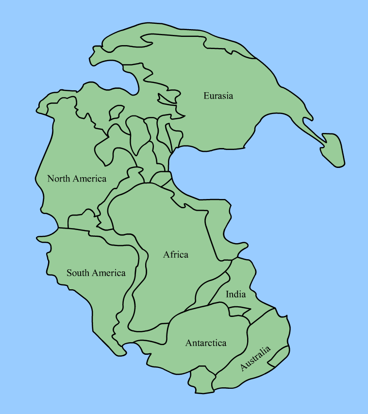
Wikipedia Commons Image.
He also proposed that Pangaea split into two parts:
1) Northern Pangaea (which includes present day North America and Eurasia) became Laurasia.
2) Southern Pangaea (including South America, Africa, India, Antarctica, and Australia) became Gondwanaland.
After Pangaea fragmented, Laurasia drifted northward and Gondwanaland drifted southward.

Wegener knew that coral reefs form near the equator, deserts form about 30° north and south of the equator, and glaciation occurs near the poles. Based upon this information, he determined the North and South Pole positions over geologic time. He called the apparent movement polar wandering.
There were two possible explanations:
1) The continents remained motionless and the poles actually moved (literal polar wandering).
2) The poles stood approximately still and the continents moved (continental drift). Wegener preferred this explanation.
Opposition to Continental Drift
-Some scientists argued that some fossils (especially fossil plants) could have been spread from one continent to another by wind or ocean currents.
-Land dwelling reptiles could have spread from continent to continent by land bridges that rose up from the seafloor (this idea was pure speculation, as no appropriate mechanism was known).
-Wegener lacked a plausible mechanism by which continents could actually drift.
-Wegener's Polar wandering might reflect true wandering of poles rather than drifting of continents.
New Evidence for Continental Drift
1) Paleomagnetism- The study of Earth’s magnetic field through time; geologists look at the way magnetic minerals in rocks preserve the magnetic field.
When a magnetic mineral crystallizes and cools below its Curie point, its magnetic alignment is locked in.
The direction of the mineral alignment gives the direction of magnetic North. The dip of the mineral alignment gives the latitudinal distance from magnetic North.
For example, Permian age rocks in North America point to an apparent magnetic North pole in Asia whereas Permian age rocks in Europe point to an apparent magnetic North Pole in Japan.
Note: Today, when geologists use the term polar wandering they are referring to an “apparent” wandering of the poles. We know that the poles themselves did not wander (although, as we shall see, the poles flipped or reversed many times throughout geologic history).
2) The continental slope- If the continental slope is taken into account, the plates fit together extremely well.
3) GPS technology- Global positioning satellites allow us to actually watch and measure the drift of the continents (1-16 cm/year).
Seafloor Spreading
Wegener thought that the seafloor remained stationary whereas the continents moved.
In contrast, in the 1960's Harry Hess proposed that the seafloor was also moving.
According to Hess, oceanic crust is produced at mid-ocean ridges and subducted at trenches. The driving force for seafloor spreading is convection (hot mantle rises near the mid-ocean ridges and cold mantle sinks near trenches).
The best evidence for sea floor spreading was provided by magnetometer surveys perpendicular to mid-ocean ridges. A zebra pattern of magnetic reversals reflects episodic flips in Earth's North and South poles.
Image from the USGS.
The zebra pattern of magnetic anomalies is symmetrical about the ridge crest.
The concept of seafloor spreading explains the age of the sea floor. Near mid-ocean ridges: sea floor is young and lacks sediment. Away from ridges: seafloor gets older and acquires a thick blanket of pelagic sediment.

The Big Picture: Plate Tectonics
By the late 1960’s, the hypotheses of continental drift and seafloor spreading had been combined into a single, unified theory of plate tectonics.
Recall that a plate is a thick, mobile slab of the Earth’s surface made of lithosphere (crust + upper mantle). Plates glide on the ductile asthenosphere.
There are 3 types of tectonic plate boundaries:
1) Divergent Plate Boundaries
Divergent plate boundaries can occur in the middle of oceans or in the middle of a continent.
The result of a divergent plate boundary is to create a new ocean basin.
When a supercontinent like Pangaea breaks up, the divergent boundary is found in the middle of a continent, marked by a continental rift.
During the rifting event, the continental crust is stretched and thinned, producing a normal fault. Topographically this results in a rift valley with a central graben.
The fault provides a pathway for basaltic magma, which rises up from the mantle to form basalt flows and cinder cones.
As divergence continues, sea water will eventually fill the split.
True oceanic crust is eventually produced at a mid ocean rift between the two diverging continents.
The trailing edge of the continent on each side of the rift becomes a passive margin.
2) Transform Boundaries
Transform boundaries involve strike-slip motion of plates (a conservative boundary).
Transform boundaries are characterized by shallow earthquakes.
The San Andreas fault is a transform boundary. A previous plate was subducted, and after subduction was complete a subsequent plate arrived with a strike-slip orientation to the mainland.
Transform boundaries also occur along the fracture zones of mid-ocean ridges.
3) Convergent Plate Boundaries
At convergent plate boundaries, two plates move towards each other.
The character of the convergent boundary depends on the types of plates that are converging:
Ocean-ocean convergence- One of the oceanic plates will subduct. The subduction results in an island chain of volcanoes called an island arc (for example, the Phillipines).
Ocean-continent convergence- The dense oceanic crust is subducted below the continental crust. A chain of volcanoes forms on the continental crust as a magmatic arc.
Regional metamorphism will occur due to the rising hot magmas and also due to the convergent forces. On the landward side of the arc, a fold and thrust belt will form.
Continent-continent convergence- In the case of continental-continental convergence, neither plate will subduct. First, ocean floor in-between them the continents is subducted. Eventually, when all the oceanic crust is subducted, the continents will collide. The two continents will weld together along a suture zone. Fold and thrust belts will form from the convergence and regional metamorphism will occur (Himalayan Mountains).
A closer look at subduction (for ocean-ocean or ocean-continent subduction).
A Benioff zone defined by shallow, intermediate, and deep earthquakes will define the top of the down-going plate.
At a depth of ~100 km, magmas will be generated in the asthenosphere overlying the down-going plate. The magmas will rise upward, creating a chain of volcanoes on the overlying plate that parallel the subduction zone.
What Causes Plate Motions?
Rock deep within the Earth’s interior is heated and rises whereas shallow, colder denser rock sinks. This sets up a convection current.
Huge convection cells may extend from the heat source at the core-mantle boundary all the way to the base of the lithosphere.
Several mechanisms assist in the movement of plates:
1) Ridge-push- Plates move apart at the midocean ridge due to down slopes.
2) Slab-pull- Subducting slabs pull the surface part of the plate away from the ridge.
3) Trench-suction- The subducting plate falls into the mantle. As a result, the overlying trench and plate are pulled horizontally, seaward, toward the subducting plate.
Mantle Plumes and Hot Spots
A modification to the convection model suggests that the mantle transfers heat in the form of narrow columns of hot rock called mantle plumes.
The mantle plumes may rise from the core-mantle boundary and stay stationary.
The mantle plumes have a wide, mushroom-shaped head and a long, narrow tail.
Mantle plumes are proposed to produce “hot-spot” volcanic activity on the earth’s surface, sometimes far away from any plate margins.
Hawaii volcanism is “hot-spot” volcanism. Hawaii is located in the middle of the Pacific plate, on oceanic crust.
Yellowstone volcanism is another example of “hot-spot” volcanism. Yellowstone is located on the North American plate in the middle of continental crust.
Hot spot volcanism fed by a mantle plume is proposed to be the reason for the breakup of Pangaea.
Friday, August 21, 2015
Thursday, August 20, 2015
Tuesday, August 18, 2015
Weathering and erosion
Weathering processes
Rock that is close to the land surface is subject to physical and chemical modification by a number of different weathering processes. These processes generally start with water percolating down into joints formed by stress release as the rock comes close to the surface, and are most intense at the surface and in the soil profile. Weathering is the breakdown and alteration of bedrock by mechanical and chemical processes that create a regolith (layer of loose material), which is then available for transport away from the site.

Physical weathering

These are processes that break the solid rock into pieces and may separate the different minerals without involving any chemical reactions. The most important agents in this process are as follows.
Freeze-thaw action
Water entering cracks in rock expands upon freezing, forcing the cracks to widen; this process is also known as frost shattering and it is extremely effective in
areas that regularly fluctuate around 0 degree Celsius, such as high mountains in temperate climates and in polar regions.

Salt growth
Seawater or other water containing dissolved salts may also penetrate into cracks, especially in coastal areas. Upon evaporation of the water, salt crystals form and their growth generates localised, but significant, forces that can further open cracks in the rock.
Temperature changes
Changes in temperature probably play a role in the physical breakdown of rock. Rapid changes in temperature occur in some desert areas where the temperature can fluctuate by several tens of degrees Celsius between day and night; if different minerals expand and contract at differentrates, the internal forces created could cause the rock to split. This process is referred to as exfoliation, as thin layers break off the surface of the rock.
Chemical weathering

These processes involve changes to the minerals that make up a rock. The reactions that can take place are as follows.
Solution
Most rock-forming silicate minerals have very low solubility in pure water at the temperatures at the
Earth’s surface and so most rock types are not susceptible to rapid solution. It is only under conditions of strongly alkaline waters that silica becomes moderately soluble. Carbonate minerals are moderately soluble, especially if the groundwater (water passing through bedrock close to the surface) is acidic. Most soluble are evaporite minerals such as halite (sodium chloride) and gypsum, which locally can form an important component of sedimentary bedrock.
Hydrolysis
Hydrolysis reactions depend upon the dissociation of H2O into H+ and OH ions that occurs when there is an acidifying agent present. Natural acids that are important in promoting hydrolysis include carbonic acid (formed by the solution of carbon dioxide in water) and humic acids, a range of acids formed by the bacterial breakdown of organic matter in soils. Many silicates undergo hydrolysis reactions, for example the formation of kaolinite (a clay mineral) from orthoclase (a feldspar) by reaction with water.
Oxidation
The most widespread evidence of oxidation is the formation of iron oxides and hydroxides from minerals containing iron. The distinctive red-orange rust colour of ferric iron oxides may be seen in many rocks exposed at the surface, even though the amount of iron present may be very small.
The products of weathering
Material produced by weathering and erosion of material exposed on continental landmasses is referred to as terrigenous (meaning derived from land). Weathered material on the surface is an important component of the regolith that occurs on top of the bedrock in most places. Terrigenous clastic detritus comprises minerals weathered out of bedrock, lithic fragments and new minerals formed by weathering processes. Rock-forming minerals can be categorised in terms of their stability in the surface environment. Stable minerals such as quartz are relatively unaffected by chemical weathering processes and physical weathering simply separates the quartz crystals from each other and from other minerals in the rock. Micas and orthoclase feldspars are relatively resistant to these processes, whereas plagioclase feldspars, amphiboles, pyroxenes and olivines all react very readily under surface conditions and are only rarely carried away from the site of weathering in an unaltered state. The most important products of the chemical weathering of silicates are clay minerals. A wide range of clay minerals form as a result of the breakdown of different bedrock minerals under different chemical conditions; the most common are kaolinite, illite, chlorite and montmorillonite. Oxides of aluminium (bauxite) and iron (mainly haematite) also form under conditions of extreme chemical weathering.
In places where chemical weathering is subdued, lithic fragments may form an important component of the detritus generated by physical processes. The nature of these fragments will directly reflect the bedrock type and can include any lithology found at the Earth’s surface. Some lithologies do not last very long as fragments: rocks made of evaporite minerals are readily dissolved and other lithologies are very fragile making them susceptible to break-up. Detritus composed of basaltic lithic fragments can form around volcanoes and broken up limestone can make up an important clastic component of some shallow marine environments.
Soil development
Soil formation is an important stage in the transformation of bedrock and regolith into detritus available for transport and deposition. In situ (in place) physical and chemical weathering of bedrock creates a soil that may be further modified by biogenic processes. The roots of plants penetrating into bedrock can enhance break-up of the underlying rock and the accumulation of vegetation (humus) leads to a change in the chemistry of the surface waters as humic acids form. Soil profiles become thicker through time as bedrock is broken up and organic matter accumulates, but a soil is also subject to erosion. Movement under gravity and by the action of flowing water may remove part or all of a soil profile. These erosion processes may be acute on slopes and important on flatter-lying ground where gullying may occur. The soil becomes disaggregated and contributes detritus to rivers. In temperate and humid tropical environments most of the sediment carried in rivers is likely to have been part of a soil profile at some stage. Continental depositional environments are also sites of soil formation, especially the floodplains of rivers. These soils may become buried by overlying layers of sediment and are preserved in the stratigraphic record as fossil soils.
Erosion and transport
Weathering is the in situ breakdown of bedrock and erosion is the removal of regolith material. Loose material on the land surface may be transported downslope under gravity, it may be washed by water, blown away by wind, scoured by ice or moved by a combination of these processes. Falls, slides and slumps are responsible for moving vast quantities of material downslope in mountain areas but they do not move detritus very far, only down to the floor of the valleys. The transport of detritus over greater distances normally involves water, although ice and wind also play an important role in some environments.
Erosion and transport under gravity

On steep slopes in mountainous areas and along cliffs movements downslope under gravity are commonly the first stages in the erosion and transport of weathered material.
Downslope movement
There is a spectrum of processes of movement of material downslope. A landslide is a coherent mass of bedrock that has moved downslope without significantly breaking up in the process. Many thousands of cubic metres of rock can be translated downhill retaining the internal structure and stratigraphy of the unit. If the rock breaks up during its movement it is a rock fall, which accumulates as a chaotic mass of material at the base of the slope. These movements of material under gravity alone may be triggered by an earthquake, by undercutting at the base of the slope, or by other mechanisms, such as water logging of a potentially unstable slope by a heavy rainfall. Movement downslope may also occur when the regolith is lubricated by water and there is soil creep. This is a much slower process than falls and slides and may not be perceptible unless a hillside is monitored over a number of years. A process that may be considered to be intermediate between creep movement and slides is slumping. Slumps are instantaneous events like slides but the material is plastic due to saturation by water and it deforms during movement downslope. With sufficient water a slump may break up into a debris flow.
Scree and talus cones
In mountain areas weathered detritus falls as grains, pebbles and boulders down mountainsides to accumulate near the bottom of the slope. These accumulations ofscree are often reworked by water, ice and wind but sometimes remain preserved as talus cones, i.e. concentrations of debris at the base of gullies. These deposits are characteristically made up of angular to very angular clasts because transport distances are very short, typically only a few hundred metres, so there is little opportunity for the edges of the clasts to become abraded. A small amount of sorting and stratification may result from percolating water flushing smaller particles down through the pile of sediment, but generally scree deposits are poorly sorted and crudely stratified. Bedding is therefore difficult to see in talus deposits but where it can be seen the layers are close to the angle of rest of loose aggregate material. Talus deposits are distinct from alluvial fans because water does not play a role in the transport and deposition.
Erosion and transport by water

Erosion by water on hillsides is initially as a sheet wash, i.e. unconfined surface run-off down a slope following rain. This overground flow may pick up loose debris from the surface and erode the regolith. The quantity of water involved and its carrying capacity depends not only on the amount of rainfall but also the characteristics of the surface: water runs faster down a steep slope, vegetation tends to reduce flow and trap debris and a porous substrate results in infiltration of the surface water. Surface run-off is therefore most effective at carrying detritus during flash-flood events on steep, impermeable slopes in sparsely vegetated arid regions. Vegetation cover and thicker, permeable soils in temperate and tropical climates tend to reduce the transport capacity of surface run-off. Sheet wash becomes concentrated into rills and gullies that confine the flow and as these gullies coalesce into channels the headwaters of streams and rivers are established. Rivers erode into regolith and bedrock as the turbulent flow scours at the floor and margins of the channel, weakening them until pieces fall off into the stream. Flow over soluble bedrock such as limestone also gradually removes material in solution. Eroded material may be carried away in the stream flow as bedload, in suspension, or in solution; the confluence of streams forms larger rivers, which may feed alluvial fans, fluvial environments of deposition, lakes or seas.
Erosion and transport by wind

Winds are the result of atmospheric pressure differences that are partly due to global temperature distributions, and also local variations in pressure due to the temperature of water masses that move with ocean currents, heat absorbed by land masses and cold air over high glaciated mountain regions. A complex and shifting pattern of regions of high pressure (anticyclones) and low pressure (depressions) regions generates winds all over the surface of the Earth. Winds experienced at the present day range up to storm force winds of 100 km to hurricanes that are twice that velocity. Winds are capable of picking up loose clay, silt and sand-sized debris from the land surface. Wind erosion is most effective where the land surface is not bound by plants and hence it is prevalent where vegetation is sparse, in cold regions, such as near the poles and in high mountains, and dry deserts. Dry floodplains of rivers, sandy beaches and exposed sand banks in rivers in any climate setting may also be susceptible to wind erosion. Eroded fine material (up to sand grade) can be carried over distances of hundreds or thousands of kilometres by the wind. The size of material carried is related to the strength (velocity) of the air current.
Erosion and transport by ice

Glaciers in temperate mountain regions make a very significant contribution to the erosion and transport of bedrock and regolith. The rate of erosion is between two and ten times greater in glaciated mountain areas than in comparable unglaciated regions. In contrast, glaciers and ice sheets in polar regions tend to inhibit the erosion of material because the ice is frozen to the bedrock: movement of the ice in these polar ‘cold-based’ glaciers is mainly by shearing within the ice body. In temperate (warm based) glaciers, erosion of the bedrock by ice occurs by two processes, abrasion and plucking. Glacial abrasion occurs by the frictional action of blocks of material embedded in the ice (‘tools’) on the bedrock. These tools cut grooves, glacial striae, in the bedrock a few millimetres deep and elongate parallel to the direction of ice movement: striae can hence be used to determine the pathways of ice flow long after the ice has melted. The scouring process creates rock flour, clay and silt-sized debris that is incorporated into the ice. Glacial plucking is most common where a glacier flows over an obstacle. On the up-flow side of the obstacle abrasion occurs but on the down-flow side the ice dislodges blocks that range from centimetres to metres across. The blocks plucked by the ice and subsequently incorporated into the glacier are often loosened by subglacial freeze-thaw action. The landforms created by this combination of glacial abrasion and plucking are called roche moutone'e, apparently because they resemble sheep from a (very) great distance.
Sunday, August 16, 2015
Paleocurrents indicators and its analysis
Paleocurrents
A palaeocurrent indicator is evidence for the direction of flow at the time the sediment was deposited, and may also be referred to as the palaeoflow. Palaeoflow data are used in conjunction with facies analysis and provenance studies to make palaeogeographic reconstructions. The data are routinely collected when making a sedimentary log, but additional palaeocurrent data may also be collected from localities that have not been logged in order to increase the size of the data set.
Palaeocurrent indicators
Two groups of palaeocurrent indicators in sedimentary structures can be distinguished. Unidirectional indicators are features that give the direction of flow.
 |
| Cross lamination |
- Cross-lamination is produced by ripples migrating in the direction of the flow of the current. The dip direction of the cross-laminae is measured.
 |
| Cross bedding |
- Cross-bedding is formed by the migration of aeolian and subaqueous dunes and the direction of dip of the lee slope is approximately the direction of flow. The direction of dip of the cross-strata in cross-bedding is measured.
- Large-scale cross-bedding and cross-stratification formed by large bars in river channels and shallow marine settings, or the progradation of foresets of Gilbert-type deltas is an indicator of flow direction. The direction of dip of the cross-strata is measured. An exception is epsilon cross-stratification produced by point-bar accumulation,which lies perpendicular to flow direction.
 |
| Clast imbrication |
- Clast imbrication is formed when discoid gravel clasts become oriented in strong flows into a stable position with one of the two longer axes dipping upstream when viewed side-on. Note that this is opposite to the measured direction in cross stratification.
 |
| Flute casts |
- Flute casts are local scours in the substrata generated by vortices within a flow. As the turbulent vortex forms it is carried along by the flow and lifted up, away from the basal surface to leave an asymmetric mark on the floor of the flow, with the steep edge on the upstream side. The direction along the axis of the scour away from the steep edge is measured.
Flow axis indicators are structures that provide information about the axis of the current but do not differentiate between upstream and downstream directions. They are nevertheless useful in combination with unidirectional indicators, for example, grooves and flutes may be associated with turbidites.
- Primary current lineations on bedding planes are measured by determining the orientation of the lines of grains.
- Groove casts are elongate scours caused by the indentation of a particle carried within a flow that give the flow axis.
- Elongate clast orientation may provide information if needle-like minerals, elongate fossils such as belemnites, or pieces of wood show a parallel alignment in the flow.
- Channel and scour margins can be used as indicators because the cut bank of a channel lies parallel to the direction of flow.
Stromatolites

Stromatolites, essentially, can indicate the heading of paleo-streams. They can frame in lengthen shapes that demonstrate the pattern of streams, or they can be slanted and unbalanced and can be utilized to focus the ability to know east from west, fundamentally landward or toward the ocean, and the introduction of the shoreline. The stromatolites in Shark Bay, Australia have been utilized to recreate a paleocurrent framework in proterozoic silt in view of their shape and introductions. It was found that their extend circular, columnar structure was parallel with the bearing of wave scour, and consequently typical to the shoreline. Although most examinations of old and current stromatolites have finished up to shape ordinary to the shoreline, some stromatolites have indicated distinctive introductions. There have been stromatolites depicted from the Proterozoic that are accepted to have framed parallel to the coastline in view of paleocurrent headings that were deciphered from related sedimentary structures. The circular state of the stromatolites are thought to have been the after effect of tidal streams running parallel to the length of a stretched embayment in the Precambrian Sea.
Measuring palaeocurrents
The most commonly used features for determining palaeoflow are cross-stratification, at various scales. The measurement of the direction of dip of an inclined surface is not always straightforward, especially if the surface is curved in three dimensions as is the case with trough cross-stratification. Normally an exposure of cross-bedding that has two vertical faces at right angles is needed, or a horizontal surface cuts through the cross-bedding. In all cases a single vertical cut through the cross-stratification is unsatisfactory because this only gives an apparent dip, which is not necessarily the direction of flow.
Imbrication of discoid pebbles is a useful palaeoflow indicator in conglomerates, and if clasts protrude from the rock face, it is usually possible to directly measure the direction of dip of clasts. It must be remembered that imbricated clasts dip upstream, so the direction of dip of the clasts will be 180 degrees from the direction of palaeoflow. Linear features such as grooves and primary current lineations are the easiest things to measure by recording their direction on the bedding surface, but they do not provide a unidirectional flow indicator. The positions of the edges of scours and channels provide an indication of the orientation of a confined flow: three dimensional exposures are needed to make a satisfactory estimate of a channel orientation, and other features such as cross-bedding will be needed to obtain a flow direction.
The procedure for the collection and interpretation of palaeocurrent data becomes more complex if the strata have been deformed. The direction has to be recorded as a plunge with respect to the orientation of the bedding, and this direction must then be rotated back to the depositional horizontal using stereonet techniques. In answer to the question of how many data points are required to carry out palaeocurrent analysis, it is tempting to say ‘as many as possible’. The statistical validity of the mean will be improved with more data, but if only a general trend of flow is required for the project in hand, then fewer will be required. A detailed palaeoenvironmental analysis is likely to require many tens or hundreds of readings. In general, a mean based on less than 10 readings would be considered to be unreliable, but sometimes only a few data points are available, and any data are better than none. Although every effort should be made to obtain reliable readings, the quality of exposure does not always make this possible, and sometimes the palaeocurrent reading will be known to be rather approximate. Once again, anything may be better than nothing, but the degree of confidence in the data should be noted.
There are several important considerations when collecting palaeocurrent data. Firstly it is absolutely essential to record the nature of the palaeocurrent indicator that has been recorded (trough cross-bedding, flute marks, primary current lineation, and so on). Secondly, the facies of the beds that contain the palaeoflow indicators is also critical: the deposits of a river channel will have current indicators that reflect the river flow, but in overbank deposits the flow may have been perpendicular to the river channel. Lastly, not all palaeoflow indicators have the same ‘rank’: due to the irregularities of flow in a channel, a ripple on a bar may be oriented in almost any direction, but the downstream face of a large sandy or gravelly bar will produce cross-bedding that is close to the direction of flow of the river. It is therefore good practice to separate palaeoflow indicators into their different ranks when carrying out analyses of the data.
Presentation and analysis of directional data
Directional data are commonly collected and used in geology. Palaeocurrents are most frequently encountered in sedimentology, but similar data are collected in structural analyses. Once a set of data has been collected it is useful to be able to determine parameters such as the mean direction and the spread about the mean (or standard deviation). The procedure used for calculating the mean of a set of directional data is described below. Palaeocurrent data are normally plotted on a rose diagram. This is a circular histogram on which directional data are plotted. The calculated mean can also be added. The base used is a circle divided up with radii at 108 or 208 intervals and containing a series of concentric circles. The data are firstly grouped into blocks of 108 or 208 (0018–0208, 021–0408, etc.) and the number that fall within each range is marked by gradations out from the centre of the circular histogram.
Mass Flow
What is Mass flow?

Mixtures of detritus and fluid that move under gravity are known collectively as mass flows, gravity flows or density currents. A number of different mechanisms are involved and all require a slope to provide the potential energy to drive the flow. This slope may be the surface over which the flow occurs, but a gravity flow will also move on a horizontal surface if it thins downflow, in which case the potential energy is provided by the difference in height between the tops of the upstream and the downstream parts of the flow.
Debris flows

Debris flows are dense, viscous mixtures of sediment and water in which the volume and mass of sediment exceeds that of water. A dense, viscous mixture of this sort will typically have a low Reynolds number so the flow is likely to be laminar. In the absence of turbulence no dynamic sorting of material into different sizes occurs during flow and the resulting deposit is very poorly sorted. Some sorting may develop by slow settling and locally there may be reverse grading produced by shear at the bed boundary. Material of any size from clay to large boulders may be present. Debris flows occur on land, principally in arid environments where water supply is sparse (such as some alluvial fans) and in submarine environments where they transport material down continental slopes and locally on some coarse-grained delta slopes. Deposition occurs when internal friction becomes too great and the flow ‘freezes’. There may be little change in the thickness of the deposit in a proximal to distal direction and the clast size distribution may be the same throughout the deposit. The deposits of debris flows on land are typically matrix-supported conglomerates although clast-supported deposits also occur if the relative proportion of large clasts is high in the sediment mixture. They are poorly sorted and show a chaotic fabric, i.e. there is usually no preferred orientation to the clasts, except within zones of shearing that may form at the base of the flow. When a debris flow travels through water it may partly mix with it and the top part of the flow may become dilute. The tops of subaqueous debris flows are therefore characterised by a gradation up into better sorted, graded sediment, which may have the characteristics of a turbidite.
Turbidity currents


Turbidity currents are gravity-driven turbid mixtures of sediment temporarily suspended in water. They are less dense mixtures than debris flows and with a relatively high Reynolds number are usually turbulent flows. The name is derived from their characteristics of being opaque mixtures of sediment and water (turbid) and not the turbulent flow. They flow down slopes or over a horizontal surface provided that the thickness of the flow is greater upflow than it is downflow. The deposit of a turbidity current is a turbidite. The sediment mixture may contain gravel, sand and mud in concentrations as little as a few parts per thousand or up to 10% by weight: at the high concentrations the flows may not be turbulent and are not always referred to as turbidity currents. The volumes of material involved in a single flow event can be anything up to tens of cubic kilometres, which is spread out by the flow and deposited as a layer a few millimetres to tens of metres thick. Turbidity currents, and hence turbidites, can occur in water anywhere that there is a supply of sediment and a slope. They are common in deep lakes, and may occur on continental shelves, but are most abundant in deep marine environments, where turbidites are the dominant clastic deposit. The association with deep marine environments may lead to the assumption that all turbidites are deep marine deposits, but they are not an indicator of depth as turbidity currents are a process that can occur in shallow water as well. Sediment that is initially in suspension in the turbidity current starts to come into contact with the underlying surface where it may come to a halt or move by rolling and suspension. In doing so it comes out of suspension and the density of the flow is reduced. Flow in a turbidity current is maintained by the density contrast between the sediment-water mix and the water, and if this contrast is reduced, the flow slows down. At the head of the flow turbulent mixing of the current with the water dilutes the turbidity current and also reduces the density contrast. As more sediment is deposited from the decelerating flow a deposit accumulates and the flow eventually comes to a halt when the flow has spread out as a thin, even sheet.
Low- and medium-density turbidity currents
The first material to be deposited from a turbidity current will be the coarsest as this will fall out of suspension first. Therefore a turbidite is characteristically normally graded. Other sedimentary structures within the graded bed reflect the changing processes that occur during the flow and these vary according to the density of the initial mixture. Low- to medium-density turbidity currents will ideally form a succession known as a Bouma sequence, named after the geologist who first described them. Five divisions are recognised within the Bouma sequence, referred to as ‘a’ to ‘e’ divisions and annotated Ta, Tb and so on.
- Ta: This lowest part consists of poorly sorted, structureless sand: on the scoured base deposition occurs rapidly from suspension with reduced turbulence inhibiting the formation of bedforms.
- Tb: Laminated sand characterises this layer, the grain size is normally finer than in ‘a’ and the material is better sorted: the parallel laminae are generated by the separation of grains in upper flow regime transport.
- Tc: Cross-laminated medium to fine sand, sometimes with climbing ripple lamination, form the middle division of the Bouma sequence: these characteristics indicate moderate flow velocities within the ripple bedform stability field and high sedimentation rates. Convolute lamination can also occur in this division.
- Td: Fine sand and silt in this layer are the products of waning flow in the turbidity current: horizontal laminae may occur but the lamination is commonly less well defined than in the ‘b’ layer.
- Te: The top part of the turbidite consists of finegrained sediment of silt and clay grade: it is deposited from suspension after the turbidity current has come to rest and is therefore a hemipelagic deposit.
Turbidity currents are waning flows, that is, they decrease velocity through time as they deposit material, but this means that they also decrease velocity with distance from the source. There is therefore a decrease in the grain size deposited with distance. The lower parts of the Bouma sequence are only present in the more proximal parts of the flow. With distance the lower divisions are progressively lost as the flow carries only finer sediment and only the ‘c’ to ‘e’ or perhaps just ‘d’ and ‘e’ parts of the Bouma sequence are deposited. In the more proximal regions the flow turbulence may be strong enough to cause scouring and completely remove the upper parts of a previously deposited bed. The ‘d’ and ‘e’ divisions may therefore be absent due to this erosion and the eroded sediment may be incorporated into the overlying deposit as mud clasts. The complete Ta to Te sequence is therefore only likely to occur in certain parts of the deposit, and even there intermediate divisions may be absent due, for example, to rapid deposition preventing ripple formation in Tc. Complete Ta-e Bouma sequences are in fact rather rare.
High-density turbidity currents
Under conditions where there is a higher density of material in the mixture the processes in the flow and hence of the characteristics of the deposit are different from those described above. High-density turbidity currents have a bulk density of at least 1.1 g/cm 3. The turbidites deposited by these flows have a thicker coarse unit at their base, which can be divided into three divisions. Divisions S1 and S2 are traction deposits of coarse material, with the upper part, S2, representing the ‘freezing’ of the traction flow. Overlying this is a unit, S3, that is characterised by fluid-escape structures indicating rapid deposition of sediment. The upper part of the succession is more similar to the Bouma Sequence, with Tt equivalent to Tb and Tc and overlain by Td and Te: this upper part therefore reflects deposition from a lower density flow once most of the sediment had already been deposited in the ‘S’ division. The characteristics of high-density turbidites were described by Lowe, after whom the succession is sometimes named.
Grain flows

Avalanches are mechanisms of mass transport down a steep slope, which are also known as grain flows. Particles in a grain flow are kept apart in the fluid medium by repeated grain to grain collisions and grain flows rapidly ‘freeze’ as soon as the kinetic energy of the particles falls below a critical value. This mechanism is most effective in well-sorted material falling under gravity down a steep slope such as the slip face of an aeolian dune. When the particles in the flow are in temporary suspension there is a tendency for the finer grains to fall between the coarser ones, a process known as kinetic sieving, which results in a slight reverse grading in the layer once it is deposited. Although most common on a small scale in sands, grain flows may also occur in coarser, gravelly material in a steep subaqueous setting such as the foreset of a Gilbert-type delta.
Saturday, August 15, 2015
Flows, sediments and bedforms
Bedform

A bedform is a morphological feature formed by the interaction between a flow and cohesion less sediment on a bed. Ripples in sand in a flowing stream and sand dunes in deserts are both examples of bedforms, the former resulting from flow in water, the latter by airflow. The patterns of ripples and dunes are products of the action of the flow and the formation of bedforms creates distinctive layering and structures within the sediment that can be preserved in strata. Recognition of sedimentary structures generated by bedforms provides information about the strength of the current, the flow depth and the direction of sediment transport. A fluid flowing over a surface can be divided into a free stream, which is the portion of the flow unaffected by boundary effects, a boundary layer, within which the velocity starts to decrease due to friction with the bed, and a viscous sublayer,a region of reduced turbulence that is typically less than a millimetre thick. The thickness of the viscous sublayer decreases with increasing flow velocity but is independent of the flow depth. The relationship between the thickness of the viscous sublayer and the size of grains on the bed of flow defines an important property of the flow. If all the particles are contained within the viscous sublayer the surface is considered to be hydraulically smooth, and if there are particles that project up through this layer then the flow surface is hydraulically rough. As will be seen in the following sections, processes within the viscous sublayer and the effects of rough and smooth surfaces are fundamental to the formation of different bedforms. The following sections are concerned mainly with the formation of bedforms in flowing water in rivers and seas, but many of the fluid dynamic principles also apply to aeolian (wind-blown) deposits.
Current ripples


Flow within the viscous sublayer is subject to irregularities known as turbulent sweeps, which move grains by rolling or saltation and create local clusters of grains. These clusters are only a few grains high but once they have formed they create steps or defects that influence the flow close to the bed surface. Flow can be visualised in terms of streamlines in the fluid, imaginary lines that indicate the direction of flow. Streamlines lie parallel to a flat bed or the sides of a cylindrical pipe, but where there is an irregularity such as a step in the bed caused by an accumulation of grains, the streamlines converge and there is an increased transport rate. At the top of the step, a streamline separates from the bed surface and a region of boundary layer separation forms between the flow separation point and the flow attachment point downstream. Beneath this streamline lies a region called the separation bubble or separation zone. Expansion of flow over the step results in an increase in pressure and the sediment transport rate is reduced, resulting in deposition on the lee side of the step.
Current ripples are small bedforms formed by the effects of boundary layer separation on a bed of sand. The small cluster of grains grows to form the crest of a ripple and separation occurs near this point. Sand grains roll or saltate up to the crest on the upstream stoss side of the ripple. Avalanching of grains occurs down the downstream or lee side of the ripple as accumulated grains become unstable at the crest. Grains that avalanche on the lee slope tend to come to rest at an angle close to the maximum critical slope angle for sand at around 308. At the flow attachment point there are increased stresses on the bed, which result in erosion and the formation of a small scour, the trough of the ripple.
Current ripples and cross-lamination

A ripple migrates downstream as sand is added to the crest and accretes on the lee slope. This moves the crest and hence the separation point downstream, which in turn moves the attachment point and trough downstream as well. Scour in the trough and on the base of the stoss side supplies the sand, which moves up the gentle slope of the stoss side of the next ripple and so a whole train of ripple troughs and crests advance downstream. The sand that avalanches on the lee slope during this migration forms a series of layers at the angle of the slope. These thin, inclined layers of sand are called cross-laminae, which build up to form the sedimentary structure referred to as cross-lamination.
 |
| Linguoid ripple |
When viewed from above current ripples show a variety of forms. They may have relatively continuous straight to sinuous crests (straight ripples or sinuous ripples) or form a pattern of unconnected arcuate forms called linguoid ripples. The relationship between the two forms appears to be related to both the duration of the flow and its velocity, with straight ripples tending to evolve into linguoid forms through time and at higher velocities. Straight and linguoid ripple crests create different patterns of cross-lamination in three dimensions. A perfectly straight ripple would generate cross-laminae that all dipped in the same direction and lay in the same plane: this is planar cross-lamination. Sinuous and linguoid ripples have lee slope surfaces that are curved, generating laminae that dip at an angle to the flow as well as downstream. As linguoid ripples migrate, curved cross-laminae are formed mainly in the trough-shaped low areas between adjacent ripple forms resulting in a pattern of trough cross-lamination.
Creating and preserving cross-lamination
 |
| Starved ripples |
Current ripples migrate by the removal of sand from the stoss (upstream) side of the ripple and deposition on the lee side (downstream). If there is a fixed amount of sand available the ripple will migrate over the surface as a simple ripple form, with erosion in the troughs matching addition to the crests. These starved ripple forms are preserved if blanketed by mud. If the current is adding more sand particles than it is carrying away, the amount of sand deposited on the lee slope will be greater than that removed from the stoss side. There will be a net addition of sand to the ripple and it will grow as it migrates, but most importantly, the depth of scour in the trough is reduced leaving cross-laminae created by earlier migrating ripples preserved. In this way a layer of cross-laminated sand is generated.
When the rate of addition of sand is high there will be no net removal of sand from the stoss side and each ripple will migrate up the stoss side of the ripple form in front. These are climbing ripples. When the addition of sediment from the current exceeds the forward movement of the ripple, deposition will occur on the stoss side as well as on the lee side. Climbing ripples are therefore indicators of rapid sedimentation as their formation depends upon the addition of sand to the flow at a rate equal to or greater than the rate of downstream migration of the ripples.
Constraints on current ripple formation
The formation of current ripples requires moderate flow velocities over a hydrodynamically smooth bed. They only form in sands in which the dominant grain size is less than 0.6 mm (coarse sand grade) because bed roughness created by coarser sand creates turbulent mixing, which inhibits the small scale flow separation required for ripple formation. Because ripple formation is controlled by processes within the viscous sublayer their formation is independent of water depth and current ripples may form in waters ranging from a few centimetres to kilometres deep. This is in contrast to most other subaqueous bedforms (subaqueous dunes, wave ripples), which are water-depth dependent. Current ripples can be up to 40 mm high and the wavelengths (crest to crest or trough to trough distances) range up to 500 mm. The ratio of the wavelength to the height is typically between 10 and 40. There is some evidence of a relationship between the ripple wavelength and the grain size, approximately 1000 to 1. It is important to note the upper limit to the dimensions of current ripples and to emphasise that ripples do not ‘grow’ into larger bedforms.
Dunes
| Sand dunes |
Beds of sand in rivers, estuaries, beaches and marine environments also have bedforms that are distinctly larger than ripples. These large bedforms are called dunes: the term ‘mega-ripples’ is also sometimes used, although this term fails to emphasise the fundamental hydrodynamic distinctions between ripple and dune bedforms. Evidence that these larger bedforms are not simply large ripples comes from measurement of the heights and wavelengths of all bedforms. The data fall into clusters which do not overlap, indicating that they form by distinct processes which are not part of a continuum. The formation of dunes can be related to large-scale turbulence within the whole flow; once again flow separation is important, occurring at the dune crest, and scouring occurs at the reattachment point in the trough. The water depth controls the scale of the turbulent eddies in the flow and this in turn controls the height and wavelength of the dunes: there is a considerable amount of scatter in the data, but generally dunes are tens of centimetres high in water depths of a few metres, but are typically metres high in the water depths measured in tens of metres.
Dunes and cross-bedding
 |
| Trough cross bedding. |
 |
| Tabular cross bedding |
The morphology of a subaqueous dune is similar to a ripple: there is a stoss side leading up to a crest and sand avalanches down the lee slope towards a trough. Migration of a subaqueous dune results in the construction of a succession of sloping layers formed by the avalanching on the lee slope and these are referred to as cross-beds. Flow separation creates a zone in front of the lee slope in which a roller vortex with reverse flow can form. At low flow velocities these roller vortices are weakly developed and they do not rework the sand on the lee slope. The cross-beds formed simply lie at the angle of rest of the sand and as they build out into the trough the basal contact is angular. Bedforms that develop at these velocities usually have low sinuosity crests, so the three-dimensional form of the structure is similar to planar cross-lamination. This is planar cross-bedding and the surface at the bottom of the cross-beds is flat and close to horizontal because of the absence of scouring in the trough. Cross-beds bound by horizontal surfaces are sometimes referred to as tabular cross-bedding. Cross-beds may form a sharp angle at the base of the avalanche slope or may be asymptotic (tangential) to the horizontal. At high flow velocities the roller vortex is well developed creating a counter-current at the base of the slip face that may be strong enough to generate ripples (counter-flow ripples), which migrate a short distance up the toe of the lee slope.
A further effect of the stronger flow is the creation of a marked scour pit at the reattachment point. The avalanche lee slope advances into this scoured trough so the bases of the cross-beds are marked by an undulating erosion surface. The crest of a subaqueous dune formed under these conditions will be highly sinuous or will have broken up into a series of linguoid dune forms. Trough cross-bedding formed by the migration of sinuous subaqueous dunes typically has asymptotic bottom contacts and an undulating lower boundary.
Constraints on the formation of dunes
Dunes range in size from having wavelengths of about 600 mm and heights of a few tens of millimetres to wavelengths of hundreds of metres and heights of over ten metres. The smallest are larger than the biggest ripples. Dunes can form in a range of grain sizes from fine gravels to fine sands, but they are less well developed in finer deposits and do not occur in very fine sands or silts. This grain size limitation is thought to be related to the increased suspended load in the flow if the finer grain sizes are dominant: the suspended load suppresses turbulence in the flow and flow separation does not occur. The formation of dunes also requires flow to be sustained for long enough for the structure to build up, and to form cross-bedding the dune must migrate. Dunescale cross-bedding therefore cannot be generated by short-lived flow events. Dunes are most commonly encountered in river channels, deltas, estuaries and shallow marine environments where there are relatively strong, sustained flows.
Bar forms
Bars are bedforms occurring within channels that are of a larger scale than dunes: they have width and height dimensions of the same order of magnitude as the channel within which they are formed. Bars can be made up of sandy sediment, gravelly material or mixtures of coarse grain sizes. In a sandy channel the surfaces of bar forms are covered with subaqueous dune bedforms, which migrate over the bar surface and result in the formation of units of cross-bedded sands. A bar form deposit is therefore typically a cross-bedded sandstone as a lens-shaped body. The downstream edge of a bar can be steep and develop its own slip-face, resulting in large-scale cross-stratification in both sandstones and conglomerates. Bars in channels are classified in terms of their position within the channel (side and alternate bars at the margins, mid-channel bars in the centre and point bars on bends: and their shape.
Plane bedding and planar lamination
Horizontal layering in sands deposited from a flow is referred to as plane bedding in sediments and produces a sedimentary structure called planar lamination in sedimentary rocks. Current ripples only form if the grains are smaller than the thickness of the viscous sublayer: if the bed is rough, the small-scale flow separation required for ripple formation does not occur and the grains simply roll and saltate along the surface. Plane beds form in coarser sands at relatively low flow velocities (close to the threshold for movement), but as the flow speed increases dune bedforms start to be generated. The horizontal planar lamination produced under these circumstances tends to be rather poorly defined.
Plane bedding is also observed at higher flow velocities in very fine- to coarse-grained sands: ripple and dune bedforms become washed out with an increase in flow speed as the formation of flow separation is suppressed at higher velocities. These plane beds produce well-defined planar lamination with laminae that are typically 5–20 grains thick. The bed surface is also marked by elongate ridges a few grain diameters high separated by furrows oriented parallel to the flow direction. This feature is referred to as primary current lineation (often abbreviated to ‘pcl’) and it is formed by sweeps within the viscous sublayer that push grains aside to form ridges a few grains high which lie parallel to the flow direction. The formation of sweeps is subdued when the bed surface is rough and primary current lineation is therefore less well defined in coarser sands. Primary current lineation is seen on the surfaces of planar beds as parallel lines of main grains which form very slight ridges, and may often be rather indistinct.
Supercritical flow
Flow may be considered to be subcritical, often with a smooth water surface, or supercritical, with an uneven surface of wave crests and troughs. These flow states relate to a parameter, the Froude number (Fr), which is a relationship between the flow velocity (y) and the flow depth (h), with ‘g’ the acceleration due to gravity. The Froude number can be considered to be a ratio of the flow velocity to the velocity of a wave in the flow. When the value is less than one, the flow is subcritical and a wave can propagate upstream because it is travelling faster than the flow. If the Froude number is greater than one this indicates that the flow is too fast for a wave to propagate upstream and the flow is supercritical. In natural flows a sudden change in the height of the surface of the flow, a hydraulic jump, is seen at the transition from thin, supercritical flow to thicker, subcritical flow.
Where the Froude number of a flow is close to one, standing waves may temporarily form on the surface of the water before steepening and breaking in an upstream direction. Sand on the bed develops a bedform surface parallel to the standing wave, and as the flow steepens sediment accumulates on the upstream side of the bedform. These bedforms are called antidunes, and, if preserved, antidune cross-bedding would be stratification dipping upstream. However, such preservation is rarely seen because as the wave breaks, the antidune bedform is often reworked, and as the flow velocity subsequently drops the sediment is reworked into upper stage plane beds by subcritical flow. Well-documented occurrences of antidune cross-stratification are known from pyroclastic surge deposits, where high velocity flow is accompanied by very high rates of sedimentation.
Subscribe to:
Posts (Atom)